Posts

Showing posts from August, 2020

What is RVDT?

Image
  RVDT is an acronym for Rotary Variable Differential Transformer and is a common type of electromechanical sensor that can convert the rotary motion of an object around an axis into a corresponding electrical signal. Construction: An RVDT consists of a hollow cylinder with a ferromagnetically conducted core rotating in clockwise and anticlockwise direction freely between the hollow cylinder.  A primary coil is wrapped around in the hollow cylinder and is energized by constant amplitude AC source known as the primary excitation. Two secondary coils having an equal number of turns are wrapped on either side of the primary coil at equal distances from the primary coil.    The two secondary coils are connected in the series generating AC output voltage.  A signal conditioning circuit that is housed inside the RVDT structure and is required to convert the output to either 5V dc or 4-20 mA’s whichever format is compatible with your data acquisition system.  Working: When the core is

What is LVDT?

Image
  LVDT is an acronym for Linear Variable Differential Transformer and is a common type of electromechanical sensor that can convert the rectilinear motion of an object along an axis into a corresponding electrical signal. Common applications that use LVDT are vibration, traction, compression, stress measurement Construction: An LVDT consists of a hollow cylinder with a shaft or push rod that moves freely back and forth inside the hollow cylinder.  The pushrod is connected to a magnetically conducted core.  A primary coil is wrapped around the middle of the hollow cylinder and is energized by constant amplitude AC source, known as the primary excitation  While two secondary coils having an equal number of turns are wrapped on either side of the cylinder at equal distances from the primary coil.    The two secondary coils are connected in the series generating AC output voltage.  A signal conditioning circuit that is housed inside the LVDT structure is required to convert the output to

Proximity sensors(video)

Image
  Subscribe  to my youtube channel and press the bell icon to receive the latest updates

Proximity sensors

Image
Proximity sensors Proximity sensors are pilot devices used to detect the presence of an object without making any physical contact and are widely used in industrial automation for the detection of objects at a position. Proximity sensors are a non-contact type of solid-state electronic devices and are normally of eddy current type or inductive, capacitive or photoelectric proximity sensor. Inductive proximity sensor An inductive proximity sensor is a non-contact proximity sensor that can detect ferrous objects that contain iron, ideally mild steel thicker than one millimeter. Construction: An inductive proximity sensor is a non-contact proximity sensor that detects ferrous objects that contain iron, ideally mild steel thicker than one millimeter.  An inductive proximity sensor consists of four major components: a ferrite core with coils , an oscillator , a detector or signal conditioner , and an output amplifier all packed in a compact housing.   The oscillator creates a symmetrical

Piezoelectric Pressure Sensor

Image
Piezoelectric Pressure Sensor A piezoelectric sensor is a device that uses the piezoelectric effect to measure changes in pressure, force, strain or temperature by converting them to an electrical charge.  The word piezo is derived from the Greek word piezein which means “Press” or “Stress”. The piezoelectric effect is observed in various materials available in different forms such as crystalline, ceramics, lead-free piezoceramics, semiconductors, and polymers. The  Lead zirconate titanate and quartz crystal are the common types of piezoelectric materials used in piezoelectric pressure sensors.  The piezoelectric material can be referred to as a bidirectional transducer as it generates an internal voltage resulting from an applied pressure or mechanical force due to piezoelectric the effect, contrarily,  it can also generate internal pressure or mechanical strain when an electric field is applied due to the inverse piezoelectric effect.  Construction: The piezoelectric pressure senso

Force measurement using load cell (video)

Image
  If you like my videos, please subscribe and press the bell icon to receive the latest updates. Share with your friends

Pressure Measurement (Video)

Image
  If you like my videos, please subscribe and press the bell icon to receive the latest updates. Share with your friends

Pressure Measurement

Image
  Pressure measurement A lot of people may have encountered pressure measurement in the day to day life, such as checking the air pressure in a tire. What most people don’t know is that they are using a pressure sensor.  Before we dive into details about pressure sensors, let’s first understand what is pressure. Pressure is an expression of a force exerted on a surface per unit area. Mathematically, the pressure is represented as: Pressure (P) = Force (F) / Unit Area (A) Units of Pressure A pressure sensor or transducer is used to measure the pressure of liquids or gases and is represented using standard unit “Pascal”.  Pascal = Newton / Meter 2 The pressure sensor monitors the pressure and can simply display it one of the several units used across the globe such as:  Pascal,  bar, PSI (pounds per square inch), atm (atmospheric pressure) Measurement of pressure inside a pipeline or a container in an industrial environment is a challenging task, keeping in mind that pressure may be very

Force measurement using cantilever beam

Image
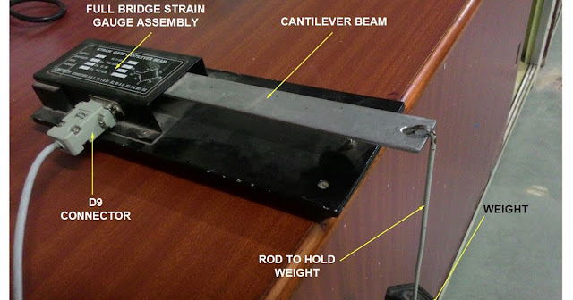
  Cantilever beam can be used for measurement up to 10 kg of weight.  One end of the cantilever is fixed, while the other end is free; the load is applied at this end, as shown in Figure below.  The strain developed can be measured by fixing strain gages at the fixed end:  two on the top side (gauge no. 1 and 3) of the beam, measuring tensile strain +ε and  two on the bottom side  (gauge no. 2 and 4)  measuring compressional strain – ε

Force measurement using load cell

Image
Force and weight relationship The weight of an object is defined as the force of gravity on the object and may be calculated as the mass times the acceleration of gravity, w = m*g. Since the weight is a force, its SI unit is the newton. For an object in free fall, so that gravity is the only force acting on it, then the expression for weight follows from Newton's second law. Force measurement using a load cell A Load cell is a force transducer intended for weight measurement that generates an electrical signal whose magnitude is directly proportional to the force being measured. Commonly types of load cells There are four common types of load cells.   Pneumatic  Hydraulic Capacitive Strain gauge  Pneumatic load cells:  Let us now understand how a pneumatic load cell works. Since it is a pneumatic load cell, we know that it will deal with air pressure. Construction:  A pneumatic load cell consists of an  elastic diaphragm attached to a platform surface where the weight will be pla