Temperature measurement

Temperature measurement
Temperature
measurement is carried out in the industry to know the temperature of the environment such as the temperature of the liquid in the furnace or winding of an electrical machine, and so on.
Temperature is
defined as a measure of the velocity of fluid particles and is a property that
determines the degree of hotness or coldness or the level of heat intensity of
a body.
The temperature
measured at absolute zero is called absolute temperature. Absolute temperature
can be obtained as
Absolute
temperature (in Kelvin) = Thermometer reading (in degree Celsius) + 273
The various instruments which are used for measuring temperature are
- Thermometers
- Bimetallic strips
- Electrical resistance thermometers (RTD)
- Thermocouple
- Thermistor
- Thermopile and
- Pyrometers which can either be total radiation pyrometer
or optical pyrometer
Thermometers
So how do we
physically measure temperature? We all know that we can measure temperature
using a thermometer. This is a very basic design and is used for 100’s of
years.
Instruments used for measuring ordinary temperatures
are known as thermometers and those for measuring high temperatures are
pyrometers.
Construction:
Thermometers consist of a sealed glass tube that is partly filled with some
liquids-like mercury or alcohol.
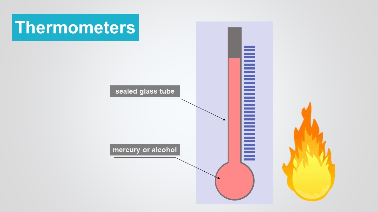
As heat is
applied, the liquid expands and rises in the glass tube. The height of the
glass tube is divided up and marked with correlative temperatures.
For example,
water boils at 100 degrees Celsius and also freezes at 0 (zero) degrees Celsius. So as
the liquid expands or contracts we can easily determine the temperature.
Advantages:
- Low cost
- Easy for human use
- Slow
- Not highly reliable and accurate
- Operates on a limited temperature range
- Most importantly, cannot facilitate digital reading
So we need fast, accurate, reliable, and digital temperature readings which will allow controllers accurately monitor and control systems.
Bimetallic strips
A bimetallic strip is a very widely used method of temperature measurement. This method is based on the principle of thermal expansion of solids when there is a change in temperature.
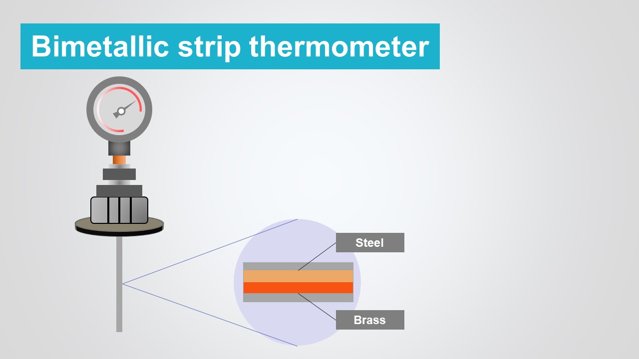
Construction
Bimetallic
strip, as the name implies, consists of two
metal strips with different degrees of thermal expansion firmly bonded
together.
Working
When the strip
is subjected to a temperature higher than the bonding temperature, the metal
strip deforms due to the different degrees of expansion in one direction. When
subjected to a temperature lower than the bonding temperature, it bends in the
other direction. The deformation is a measure of the temperature and can be
read off a calibrated scale.
Due to their
metallic materials, bimetallic thermometers can be used at temperatures from
below -100 °C to more than 500 °C.
Bimetal strips
are produced by rolling the different metal sheets one on top of the other and
then heating them so that the metals bond at the joint by diffusion processes
(cold welding).
Note: Due to the electrical conductivity of the bimetallic strip, it is also frequently used as
a safety component for automatic shutdown. Bimetallic strips can be found in
kettles, for example, which switches off the kettle automatically by opening
the electric circuit when the temperature is too high (or when the boiling
point is reached).
Types of
bimetallic thermometer
The longer the
bimetal, the greater the bend and thus the sensitivity for temperature
measurement. For this reason, a long bimetal strip is often wrapped into a
coil. Depending on whether the bimetallic coil is twisted like a spiral or a
screw (helix), two different types can be distinguished.
Spiral type
bimetallic thermometer
The design of a bimetal thermometer is to wrap the bimetallic strip into a spiral.
The inner end of the spiral is firmly connected to the housing. A pointer is
attached to the outer end of the spiral. The measured temperature can then be
read off a calibrated scale.
Such a design using a bimetallic spiral is not only very space-saving but also cost-effective. However, the disadvantage is that the dial and the temperature sensor are not separated from each other. The entire bimetal thermometer must therefore be located directly in the medium whose temperature is to be measured. Such thermometers are used, for example, in refrigerators
Helical type
bimetallic thermometer
In many cases it
is necessary to spatially separate the indicator (pointer) from the sensor
(bimetallic coil). For example, if the water temperature is to be measured in a
heating pipe, as is usual in heating systems. The temperature sensor must then
be located inside the pipe, while the display for the temperature must be
outside the pipe. Or in the food industry it is also necessary to separate the
display from the sensor if, for example, the temperature inside the food has to
be measured (“piercing thermometer”). or freezers or to determine the room
temperature.
In these cases,
bimetal thermometers are equipped with a bimetal strip wrapped into a helical
coil. The helical bimetal is firmly connected at one end to the inside of a
measuring tube (the bimetal is attached to a cylindrical pin, which is pressed
firmly into the stem). A rotatable metal rod is guided through this helical
coil, which is connected to it at the loose end. A pointer is attached to the
upper end of the metal rod. If the measuring tube is now heated, the helical
bimetal winds up and rotates the metal rod. On a calibrated scale the
corresponding temperature can be read off.
- Bimetallic strips are frequently used in simple ON-OFF switches.
- The bimetallic strips are also used in control switches.
Advantages:
- It is less costly as compared to other temperature measuring instruments.
- They have negligible maintenance.
- They have a stable operation over extended periods of time.
- The accuracy of this type of instrument is between 2% and 5% of the scale
Disadvantages:
- They are not suitable for temperatures of more than 400 °C.
- Permanent deformation of the metallic strip may occur.
RTD (Electrical Resistance Thermometer)
An RTD
(Resistance Temperature Detector) is a transducer whose resistance varies with
temperature. An RTD is a passive device which means it does not produce an
output on its own. External electronic devices are used to measure the
resistance of the transducer by passing a small electrical current through the
transducer to generate a voltage.

Big amount of
external current can cause excessive power dissipation in the resistor of RTD
and lead to excess heat, so to avoid this type of error, the current should be
kept at a minimum level.
This wiring diagram
shows the simplest application of an RTD, called “two-wire” configuration. 3
wire and 4 wire configurations provide more accurate measurements.
Construction:
The material
used for RTD’s is nickel, iron, platinum, copper, lead, tungsten, mercury,
silver, etc… One of the most common RTDs is “PT100” which consists of a thin
film of Platinum on a plastic film and shows a resistance of 100Ω at 32°F. It
offers excellent linear resistance-temperature over the range -300oC
and 1560oC.

Callendar-Van Dusen Equation
The relationship between platinum RTD resistance and temperature is described by the Callendar-Van Dusen (CVD) equation. Equation 1 shows the resistance for temperatures below 0°C and Equation 2 shows the resistance for temperatures above 0°C for a PT100 RTD.

Two-wire transmitters are typically used in applications where accuracy is not critical. The two-wire configuration allows for the simplest measurement technique but suffers from an inherent inaccuracy due to the resistance of the sensor leads. In the two-wire configuration, there is no way to directly compensate for the resistance of the lead wires which will cause an offset increase in the resistance measurement.

Three-wire transmitters are built with a compensation loop to allow the measurement to factor out the resistance of the leads. With this configuration, the controller/measurement device makes two measurements. The first measurement measures the total resistance of the sensor and the connecting lead wires. The second measurement is the resistance of the compensation loop resistance. By subtracting the compensation loop resistance from the total resistance, an account net resistance is determined. Three-wire sensors are the most common and give a good combination of accuracy and convenience.
The four-wire transmitters configuration and measurement techniques allow measurement of the sensor resistance without the influence of the lead wires. While this technique gives the best accuracy, many industrial controllers/measurement devices cannot make a true four-wire measurement.
The transition from the sensor lead wires to the field wiring is typically done in a connection head attached to the sensor. Terminal blocks are used to facilitate the connection.
RTDs are used in the form of thin films, wire wound, or coil. They are generally made of metals such as platinum, nickel, or nickel-copper alloys. The platinum wire held by a high-temperature glass adhesive in a ceramic tube is used to measure the temperature in a metal furnace.
Other applications are:
- Air conditioning and refrigeration servicing
- Food Processing
- Stoves and grills
- Textile production
- Plastics processing
- Petrochemical processing
- Microelectronics
- Air, gas, and liquid temperature measurement in pipes and tanks
- Exhaust gas temperature measurement
Advantages:
- A high degree of accuracy
- RTD’s are interchangeable in a process without recalibration or compensation
- Fast response time
Thermistors
Thermistors are
temperature-sensitive variable resistors made of ceramic-like semiconducting
materials such as metal oxides, cobalt, copper, nickel, and are widely used in
industrial purposes, for:
- Over-current protection
- Self-regulating heating elements
- Inrush current limiters

Thermistors can
be NTC or PTC.
In NTC (Negative
Temperature Coefficient) thermistors, resistance decreases as temperature
rises. NTC’s are commonly used as inrush current limiters. While in PTC
(Positive Temperature Coefficient) thermistors, resistance increases as
temperature increases. PTC thermistors are commonly used as overcurrent
protection and in resettable fuses.
Applications of Thermistors
- To monitor the coolant temperature and/or oil temperature inside the engine
- To monitor the temperature of an incubator
- Thermistors are used in modern digital thermostats
- To monitor the temperature of battery packs while charging
- To monitor temperature of hot ends of 3D printers
- To maintain the correct temperature in the food handling and processing industry equipment
- To control the operations of consumer appliances such as toasters, coffee makers, refrigerators, freezers, hairdryers, etc.
Thermocouples
The most common method of temperature measurement uses thermocouples and is based on the seeback effect.

Construction:
Seeback effect: When two dissimilar metals are joined together an emf will exist between two points which is primarily a function of the junction temperature. This principle is known as seeback effect.
Thus if both the junctions are at the same temperature there is no emf. If, however, there is a difference in temperature between the two junctions, there is an emf. The value of this emf 'E' depends on the two metals concerned and the temperature 't' of both junctions. Usually, one junction is held at 0oC and then, to a reasonable extent, the following relationship holds:
E = at + bt2
Thermocouples
need a reference measurement point called “Cold Junction”. The thermocouple
junction is often exposed to extreme environments, while the cold junction is
often mounted near the instrument location.
In comparison
with RTDs, Thermocouples are self-powered and require no external excitation
current source.
Thermocouples
are commonly used for furnaces, Gas Turbine combustion chamber,
high-temperature exhaust ducts, etc.
The main
restriction of Thermocouples is the “accuracy” which doesn’t make it the best
solution for precise applications.
Applications of Thermocouples
- To monitor temperatures and chemistry throughout the steelmaking process
- Testing temperatures associated with process plants e.g. chemical production and petroleum refineries
- Testing of heating appliance safety
- Temperature profiling in ovens, furnaces, and kilns
- Temperature measurement of gas turbine and engine exhausts
- Monitoring of temperatures throughout the production and smelting process in the steel, iron, and aluminum industry
Comparison of various temperature sensors
Let’s understand
how to select temperature sensors for appropriate applications.
Bimetallic
strips are economical and can be selected for low-cost projects. If accuracy is
required in is considered as the key performance indicator, usually, RTD’s are
better than Thermocouples; approximately 10 times more accurate.
From the
“sensitivity” point of view, while both RTDs and Thermocouples respond quickly
to temperature changes, at similar costs, thermocouples are often faster.
Thermistors can
be selected if temperature measurement is to be carried out in a small space.


Comments
Post a Comment