Hydraulic gear pumps
Hydraulic gear pumps:
- The gear pumps are robust and simple positive displacement pumps.
- It has two meshed gears revolving about their respective axes. These gears are the only moving parts in the pump.
- They are compact, relatively inexpensive, and have few moving parts.
- The rigid design of the gears and houses allow for very high pressures and the ability to pump highly viscous fluids.
- They are suitable for a wide range of fluids and offer self-priming performance.
- Sometimes gear pumps are designed to function as either a motor or a pump.
- This pump includes helical and herringbone gear sets (instead of spur gears), lobe-shaped rotors similar to roots blowers (commonly used as superchargers), and mechanical designs that allow the stacking of pumps.
- Based on the design, the gear pumps are classified as:
- External gear pumps
- Internal gear pumps
- Lobe pumps
- Gerotor pumps
Generally, gear pumps are used to pump:
- Petrochemicals: Pure or filled bitumen, pitch, diesel oil, crude oil, lube oil, etc.
- Chemicals: Sodium silicate, acids, plastics, mixed chemicals, isocyanates, etc.
- Paint and ink
- Resins and adhesives
- Pulp and paper: acid, soap, lye, black liquor, kaolin, lime, latex, sludge, etc.
- Food: Chocolate, cacao butter, fillers, sugar, vegetable fats and oils, molasses, animal food, etc.
External gear pump
Construction:
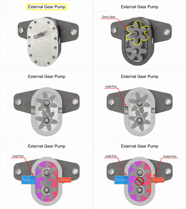
- The external gear pump consists of externally meshed two gears housed in a pump case as shown in Figure 1.
- One of the gears is coupled with a prime mover and is called driving gear and another is called driven gear.
- The rotating gear carries the fluid from the tank to the outlet pipe.
- The suction side is towards the portion whereas the gear teeth come out of the mesh.
Figure 1: External gear pump
Working:- When the gears rotate, the volume of the chamber expands leading to a pressure drop below atmospheric value. Therefore the vacuum is created and the fluid is pushed into the void due to atmospheric pressure.
- The fluid is trapped between the housing and rotating teeth of the gears.
- The discharge side of the pump is towards the portion where the gear teeth run into the mesh and the volume decreases between meshing teeth.
- The pump has a positive internal seal against leakage; therefore, the fluid is forced into the outlet port.
- The gear pumps are often equipped with a side wear plate to avoid the leakage.
- The clearance between gear teeth and housing and between the side plate and gear face is very important and plays an important role in preventing leakage. In general, the gap distance is less than 10 micrometers. The amount of fluid discharge is determined by the number of gear teeth, the volume of fluid between each pair of teeth, and the speed of rotation.
- High speed/pressure,
- Quiet operation,
- Variety of build material options
Limitations:
- The important drawback of the external gear pump is the unbalanced side load on its bearings.
- It is caused due to high pressure at the outlet and low pressure at the inlet which results in slower speeds and lower pressure ratings in addition to reducing the bearing life.
- Gear pumps are most commonly used for hydraulic fluid power applications and are widely used in chemical installations to pump fluid with a certain viscosity.
Internal gear pumps:
Internal gear pumps are exceptionally versatile. They are often used for low or medium viscosity fluids such as solvents and fuel oil and a wide range of temperatures. This is non-pulsing, self-priming, and can run dry for short periods. It is a variation of the basic gear pump.
Construction:
- It comprises of internal gear, a regular spur gear, a crescent-shaped seal, and external housing.
- The schematic of the internal gear pump is shown in Figure 2.
Figure 2: Internal gear pump
- Liquid enters the suction port between the rotor (large exterior gear) and idler (small interior gear) teeth.
- Liquid travels through the pump between the teeth and crescent.
- Crescent divides the liquid and acts as a seal between the suction and discharge ports.
- When the teeth mesh on the side opposite to the crescent seal, the fluid is forced out through the discharge port of the pump.
- This clearance between gears can be adjusted to accommodate high temperatures, to handle high viscosity fluids, and to accommodate the wear.
- These pumps are bi-rotational so that they can be used to load and unload the vessels.
Advantages:
As these pumps have only two moving parts and one stuffing box, therefore they are- Reliable
- Simple to operate
- Easy to maintain
- Provide smooth/pulseless flow
- Not suitable for high-speed and high-pressure applications.
- Only one bearing is used in the pump therefore overhung load on shaft bearing reduces the life of the bearing
- Higher cost
- Limited size range
Applications:
Some common internal gear pump applications are:
- All varieties of fuel oil and lube oil
- Resins and Polymers
- Alcohols and solvents
- Asphalt, Bitumen, and Tar
- Polyurethane foam (Isocyanate and polyol)
- Food products such as corn syrup, chocolate, and peanut butter
- Paint, inks, and pigments
- Soaps and surfactants
- Glycol
Lobe gear pumps:
Construction:
- Lobe pumps work on a similar principle of working like that of external gear pumps. However, in Lobe pumps, the lobes do not make any contact like an external gear pump (see Figure3).
- Lobe contact is prevented by external timing gears located in the gearbox.
Figure 3: Lobe gear pump
- Similar to the external gear pump, the lobes rotate to create expanding volume at the inlet. Now, the fluid flows into the cavity and is trapped by the lobes.
- Fluid travels around the interior of the casing in the pockets between the lobes and the casing.
- Finally, the meshing of the lobes forces the liquid to pass through the outlet port.
- The bearings are placed out of the pumped liquid. Therefore the pressure is limited by the bearing location and shaft deflection.
Advantages:
- High efficiency
- High Reliability
- Corrosion resistance
- Good clean-in-place and steam-in-place (CIP/SIP) characteristics,
Limitations:
- Loading characteristics are not as good as other designs, and suction ability is low.
- High-viscosity liquids require reduced speeds to achieve satisfactory performance. The reduction in speed can be 25% or more in case of high viscosity fluid.
Applications:
- Lobe pumps are widely used in industries such as pulp and paper, chemical, food, beverage, pharmaceutical, and biotechnology, etc.
- These pumps can handle solids (e.g., cherries and olives), slurries, pastes, and a variety of liquids. A gentle pumping action minimizes product degradation.
- They also offer continuous and intermittent reversible flows.
- Flow is relatively independent of changes in process pressure and therefore, the output is constant and continuous.
- Lobe pumps are frequently used in food applications because they handle solids without damaging the product.
- Large-sized particles can be pumped much effectively than in other positive displacement types. As the lobes do not make any direct contact therefore, the clearance is not as close as in other Positive displacement pumps. This specific design of the pump makes it suitable to handle low viscosity fluids with diminished performance.


Comments
Post a Comment