Posts

Vane pumps

Image
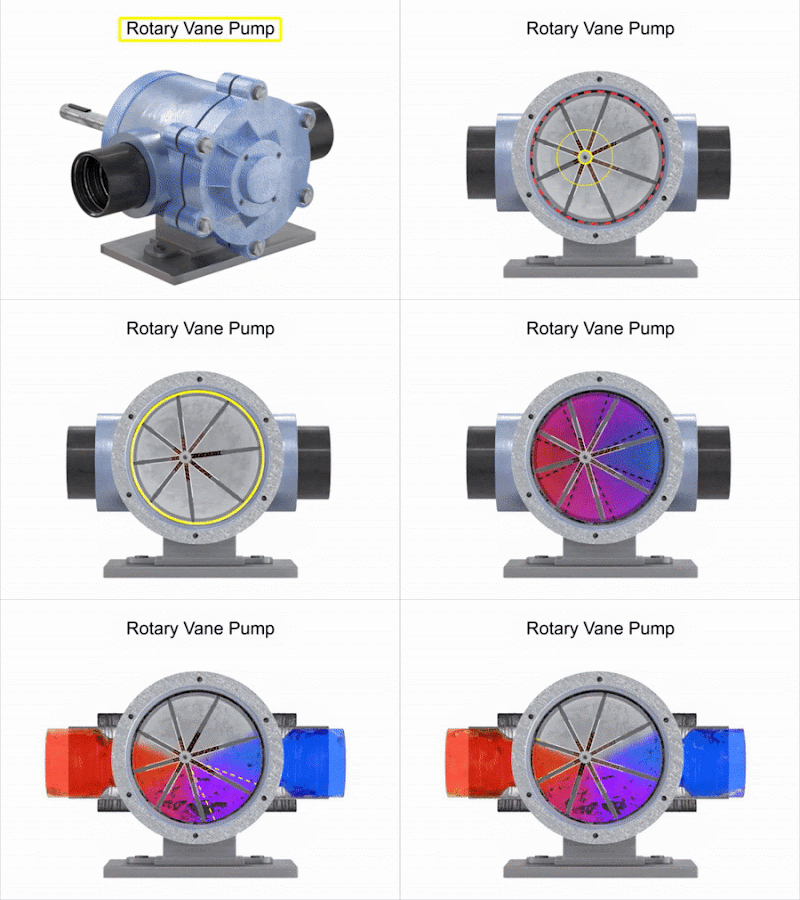
 Vane pumps Gear pumps have a disadvantage of small leakage due to the gap between gear teeth and the pump housing. These limitations are overcome in vane pumps.  The leakage is reduced by using spring or hydraulically loaded vanes placed in the slots of the driven rotor.  Capacity and pressure ratings of a vane pump are generally lower than the gear pumps, but reduced leakage gives an improved volumetric efficiency of around 95%. Types: Vane pumps are available in a number of vane configurations including  sliding vane,  flexible vane, swinging vane,  rotary vane, and  external vane, etc.  Each type of vane pump has its own advantages.  External vane pumps can handle large solids.  Flexible vane pumps can handle only the small solids but create a good vacuum.  Sliding vane pumps can run dry for short periods of time and can handle small amounts of vapor.  The vane pumps are known for their dry priming, ease of maintenance, and good suction characteristics. The operating range of these

Hydraulic gear pumps

Image
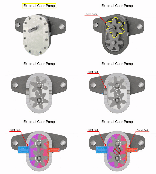
 Hydraulic gear pumps: The gear pumps are robust and simple positive displacement pumps.  It has two meshed gears revolving about their respective axes. These gears are the only moving parts in the pump.  They are compact, relatively inexpensive, and have few moving parts.  The rigid design of the gears and houses allow for very high pressures and the ability to pump highly viscous fluids.  They are suitable for a wide range of fluids and offer self-priming performance.  Sometimes gear pumps are designed to function as either a motor or a pump.  This pump includes helical and herringbone gear sets (instead of spur gears), lobe-shaped rotors similar to roots blowers (commonly used as superchargers), and mechanical designs that allow the stacking of pumps.  Based on the design, the gear pumps are classified as: External gear pumps  Internal gear pumps Lobe pumps Gerotor pumps Generally, gear pumps are used to pump: Petrochemicals: Pure or filled bitumen, pitch, diesel oil, crude oil, lub

Hydraulic Pumps

Image
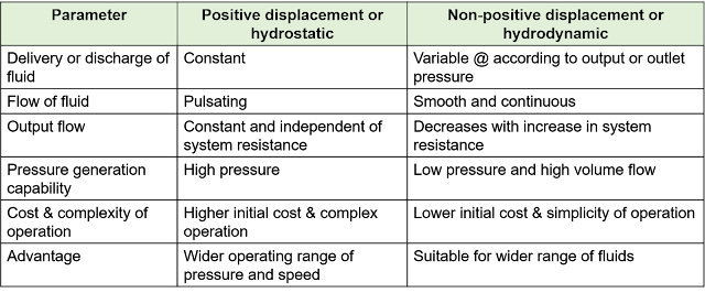
Hydraulic Pumps The electric driving motor combined with the pumping is known as a hydraulic pump (in most pieces of literature, it is referred to as a  motor-driven pump also). The hydraulic pump takes hydraulic fluid (mostly some oil) from the storage tank and delivers it to the rest of the hydraulic circuit.  In general, the speed of the pump is constant and the pump delivers an equal volume of oil in each revolution.  The amount and direction of fluid flow is controlled by some external mechanisms.  In some cases, the hydraulic pump itself is operated by a servo-controlled motor but it makes the system complex.  The hydraulic pumps are characterized by its  flow rate capacity,  power consumption,  drive speed,  the pressure delivered at the outlet and  the efficiency of the pump.  The pumps are not 100% efficient.  The efficiency of a pump can be specified in two ways.   One is the volumetric efficiency which is the ratio of the actual volume of fluid delivered to the maximum the

Hydraulic Filters

Image
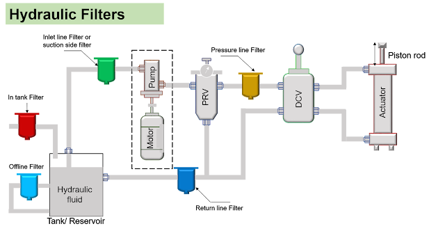
Need for filters in fluid power systems Moving parts in fluid power systems are subject to wear from contamination. Neither atmospheric air nor hydraulic fluids are clean enough as supplied to avoid this and they both become more contaminated with use.  Therefore all fluid power systems require filters to remove contamination and thereby increase component life.  Normally, filters are used to prevent dirt or dust from entering important elements of the hydraulic system such as valves, seals, etc. Hydraulic filters:  Filters are used to remove very fine particles and can be installed in various places as shown in  Figure 1. The various types of filters are as follows: Inlet line filters or suction side filters: Inlet line filters or suction side filters are located before the hydraulic pump, these filters are designed to protect the pump from harmful contaminants that are within the hydraulic fluid. The filtering media within this type of filter is typically one with a higher micron ra

Fluid contamination- sources, processes and effects on system.

Sources of contamination in the manufacturing process: Manufacturing contamination can be resulted from : Components ports not plugged Components stored in a bad environment Pumps/motors prefilled with dirty or unfiltered oil Use of floor dry or similar oil absorbents in shop areas Dirty hands, shop rags & lint used during assembly Dirty workbenches Dirty oil in test bench use to performance check components Welding and fabrication contaminate Broken tools during manufacturing Fittings laying around and not cleaned Dirty hoses from the assembly that were not cleaned and capped Assembly in a fabrication environment Dirty manufacturing procedures Dirty cutting fluid Improper flushing techniques Is a high enough velocity used to create flow turbulence when flushing parts? Dirty ports plugs Shop rags used to plug ports Not cleaning around ports before removing plugs for assembly Reservoirs not cleaned properly before assembly Filters on the shelve but not in sealed con The Process That

Comparison of hydraulic and pneumatic systems

Image
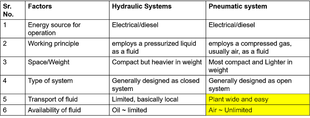
Comparison of hydraulic and pneumatic systems It is important to consider various points for comparing pneumatic systems with hydraulic systems such as power level, noise level, cleanliness, speed, accuracy, temperature effects, etc. Principal advantages and distinguishing characteristics of pneumatic and hydraulic systems are listed below: Availability: Air is available everywhere in unlimited quantities. Transport: Air and hydraulic fluid can be easily transported over large distances through pipelines. Storage: Compressed air can be stored in a reservoir and removed as required. Hydraulic oil can be stored in accumulators. Temperature: Compressed air is relatively sensitive to temperature fluctuations, whereas hydraulic fluids are relatively insensitive. Explosion-proof: Compressed air offers minimal risk of explosion or fire.  Cleanliness: Any unlubricated air which escapes through leaking pipes or components does not cause contamination. Components: The operating components

Pneumatic Systems

Image
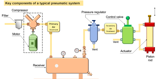
 Pneumatic Systems Pneumatic technology deals with the study of behavior and applications of compressed air in our daily life in general and manufacturing automation in particular.  Systems using compressed air for power transmission are called pneumatic systems. When air is compressed and stored, it can be used as a medium for carrying out mechanical work, measurement, and controlling and operating equipment and machines. Figure 1 shows how an extend and retract system can be implemented using pneumatics. Pneumatic systems use air (which is compressed) as the medium which is abundantly available in the atmosphere and can be easily exhausted into the atmosphere after completion of the assigned task. Figure 1. Key components of a typical pneumatic system            A pneumatic system essentially consists of following motor-driven compressor, air receiver;  directional control valve (DCV); pneumatic cylinder. Let us see the operation of each component in detail Air filters: These are us